Comece com dois limites separados.
Um controlador MPPT possui dois limites elétricos que são fáceis de confundir. A entrada fotovoltaica deve permanecer abaixo de sua tensão máxima, enquanto a saída da bateria deve permanecer abaixo de sua corrente de carga contínua nominal. A potência nominal do painel não comprova nenhuma dessas condições.
A primeira tarefa de projeto é reunir os valores de Voc, Vmp, coeficiente de temperatura, corrente de curto-circuito e potência nominal do módulo. Adicione o número de módulos em série e em paralelo, a faixa de tensão da bateria e a janela de operação do controlador. Esses valores devem ser compilados em uma planilha antes de comparar os preços dos modelos.
- A tensão fotovoltaica é um problema relacionado ao layout das strings e à temperatura.
Verificação prática 1
- A corrente de carga é um problema de conversão, bateria e fiação.
- As classificações de proteção devem ser verificadas em ambos os lados do controlador.
Calcule o limite de tensão a frio.
Por que Voc é mais importante que a tensão nominal?
A tensão de circuito aberto aumenta à medida que a temperatura da célula diminui. Um módulo de "12 V" pode ter uma Voc muito acima de 12 V, e uma string em série multiplica esse valor. Use a temperatura mínima de projeto para o local, não a temperatura média de inverno. Manhãs claras e frias podem gerar a tensão mais alta, mesmo quando o conjunto de células está produzindo pouca energia.
Uma estimativa prática é Voc,frio = Voc,STC x [1 + coeficiente de temperatura absoluto x (25 – Tmin)]. Use o coeficiente e o sinal exatamente como fornecidos na folha de dados do módulo. Em seguida, deixe uma margem abaixo da tensão máxima fotovoltaica do controlador para tolerância de medição, variação de instalação e futura substituição do módulo.
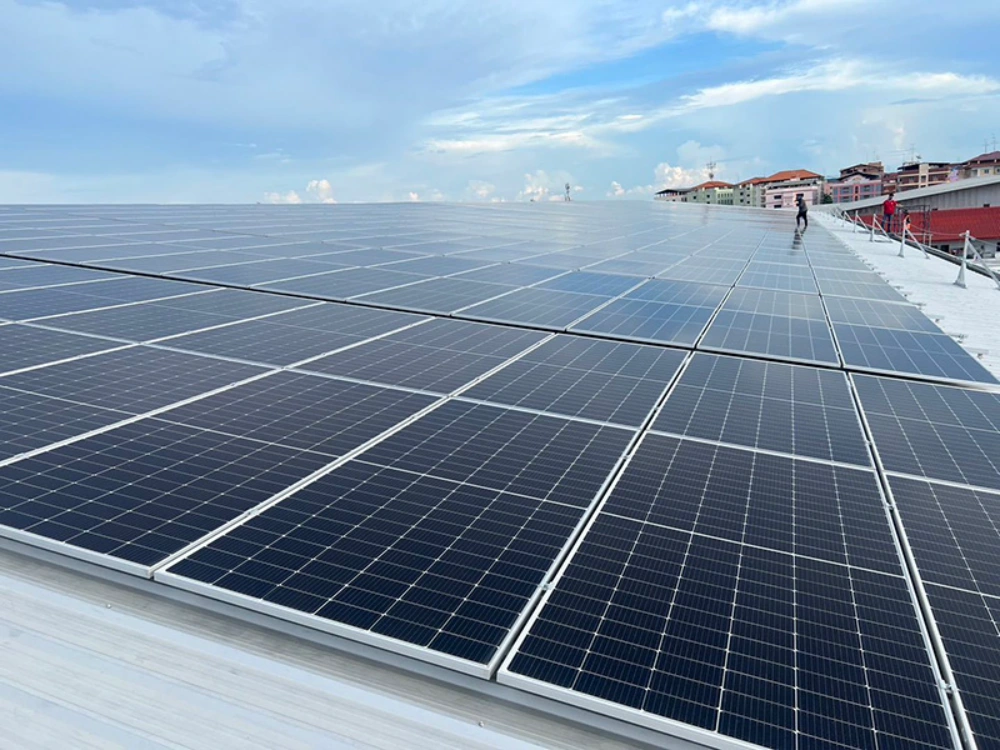
O O mais breve possível Mono A painel fotovoltaico é especificado por seu Voc, Vmp, coeficiente de temperatura e limites de corrente. Esses valores pertencem ao cálculo da string antes que a contagem da série seja aprovada.
Confirme o Vmp ativo e a janela de rastreamento.
A alta temperatura cria o risco oposto. A tensão das células cai à medida que a temperatura aumenta, portanto, uma string pode permanecer abaixo da tensão máxima fotovoltaica, mas cair abaixo da tensão mínima de MPPT ou de inicialização do controlador. Verifique a Vmp na temperatura máxima esperada das células, incluindo o calor do telhado e condições de pouco vento.
A perda de tensão nos cabos pode reduzir a tensão de operação. Longos trechos de cabos instalados no telhado, condutores subdimensionados e conectores aquecidos diminuem a tensão que chega ao controlador. Inclua a queda de tensão esperada na verificação do lado energizado, especialmente quando o projeto utiliza poucos módulos em série.
Um controlador com uma ampla janela de operação MPPT oferece mais flexibilidade de layout, mas não elimina a necessidade de calcular Voc frio e Vmp quente.
Converter energia fotovoltaica em corrente para baterias.
A bateria recebe a energia convertida, não a corrente impressa no módulo fotovoltaico. Estime a corrente máxima de carga multiplicando a potência do painel fotovoltaico pela eficiência do controlador e dividindo o resultado pela tensão mínima de carga da bateria. Ao adicionar cargas CC simultâneas, considere a tensão da bateria no momento em que a corrente de carga for máxima.
Compare o resultado com a classificação de saída do controlador, o limite de carga do fabricante da bateria, o limite do BMS, a barra de distribuição, o fusível, o disjuntor e a capacidade de corrente contínua do cabo. Um banco de baterias de 48 V pode exigir várias vezes mais corrente do que uma string fotovoltaica de alta tensão para a mesma potência. O aumento térmico e a queda de tensão devem ser calculados, e não estimados.
- Verifique o desempenho da bateria em níveis de carga baixos e altos.
Verificação prática 2
- A capacidade de interrupção do fusível deve ser dimensionada de acordo com a corrente de falha da bateria.
- Registre o comprimento do condutor, o trajeto, a temperatura ambiente e o método de terminação.
Decida se o sobredimensionamento do sistema fotovoltaico é intencional.
Painéis fotovoltaicos adicionais podem melhorar a captação de energia durante períodos de baixa incidência solar e nas estações de transição. No entanto, também podem causar distorção por recorte (clipping), aumento da corrente de curto-circuito ou sobrecarga térmica. O superdimensionamento é aceitável somente dentro dos limites específicos de tensão, corrente, distorção por recorte e condições ambientais de cada modelo.
Inclua a faixa de corte esperada na especificação. Se a bateria estiver cheia ao meio-dia, painéis fotovoltaicos adicionais podem adicionar pouca energia; se o problema for a energia no inverno, um conjunto maior de painéis pode valer a pena. Se a corrente de carregamento da bateria for o gargalo, adicionar painéis não resolve o problema. Um controlador diferente ou um sistema coordenado de geração de energia fotovoltaica pode ser uma solução. solução de inversor solar híbrido Essa pode ser a arquitetura correta.
Encomende o projeto com base no cálculo.
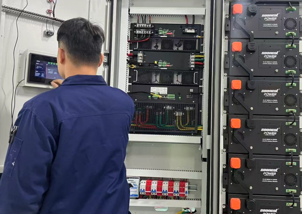
O comissionamento deve reproduzir as premissas que justificaram a compra. Meça a tensão da string antes da conexão, a tensão de operação do painel fotovoltaico, a corrente da bateria durante forte irradiação, a temperatura do controlador, a queda de tensão no cabo e qualquer evento de recorte ou alarme.
Fotografe as etiquetas dos cabos, as classificações dos fusíveis e as terminações dos cabos. Confirme se a quantidade de conexões em série e em paralelo instaladas corresponde ao desenho aprovado. Guarde o registro completo para as equipes de serviço; a substituição de um painel ou a alteração da tensão da bateria pode invalidar as margens originais.
Para projetos recorrentes, utilize valores-alvo e limites de aceitação. Isso proporciona às equipes de compras, instalação e serviço a mesma definição de um controlador aprovado.
Proteção coordenada em ambos os lados do Distrito de Columbia.
A proteção do lado fotovoltaico baseia-se na corrente da string, na exposição à corrente reversa, na seção transversal do condutor e no número de strings em paralelo. A proteção do lado da bateria enfrenta uma corrente de falha disponível muito maior. Um fusível adequado para uma string fotovoltaica pode ser totalmente inadequado para uso próximo a um banco de baterias de lítio.
Especifique os isoladores com classificação CC, a capacidade de interrupção do fusível, a capacidade de condução de corrente do condutor, os limites de temperatura dos terminais e as condições do invólucro. A proteção deve isolar uma falha sem exceder as especificações do controlador ou do cabo que o conecta.
Ajuste o perfil de carregamento à bateria.
A corrente de saída do controlador só é útil quando a bateria a suporta. Sistemas de lítio podem reduzir a corrente de carga através do BMS próximo aos limites de temperatura ou estado de carga. Bancos de baterias de chumbo-ácido podem exigir um longo estágio de absorção, o que altera a carga térmica mesmo quando a corrente de pico é menor.
Confirme as configurações de carga inicial, absorção, flutuação, equalização, corte por baixa temperatura e reinicialização com o fabricante da bateria. Uma etiqueta de voltagem compatível não garante um perfil de carregamento compatível.
Leve em consideração a diferença de tonalidade, a sombra e a perda de cabo.
Sombras parciais podem ativar diodos de bypass e reduzir a tensão efetiva da string. Incompatibilidade entre módulos, sujeira, resistência dos conectores e cabos longos também alteram o ponto de operação. Uma string que, em teoria, opera confortavelmente dentro da faixa de MPPT pode ficar próxima ao limite inferior em condições de alta temperatura e sombra.
Antes de definir a quantidade de séries, revise o layout do telhado e o trajeto dos cabos. Durante o comissionamento, meça a tensão de operação sob sombra representativa quando o local apresentar parapeitos, árvores, antenas ou múltiplas orientações de telhado.
Transforme o cálculo em um registro de aceitação.
O documento de compra deve incluir as fichas técnicas dos componentes, as temperaturas de projeto, as fórmulas, as margens, as premissas para os cabos e os níveis de proteção. Registre a revisão exata do módulo, pois um painel posterior com a mesma potência pode apresentar valores diferentes de Voc, Vmp ou coeficientes de temperatura.
Utilize valores alvo e de rejeição separados. O valor alvo descreve a operação preferencial; o valor de rejeição define quando a fiação, a contagem de strings, a seleção do controlador ou as configurações da bateria devem ser corrigidas antes da transferência.
Diagnosticar baixa colheita sem adivinhação
Um consumo de energia inferior ao esperado não indica automaticamente uma falha no controlador. A bateria pode atingir seu limite de carga prematuramente, o arranjo pode apresentar recorte intencional ou a tensão Vmp em alta temperatura pode estar próxima do limite de rastreamento. Perda de sinal nos cabos e sombreamento podem causar sintomas semelhantes.
Compare a tensão fotovoltaica medida, a corrente da bateria, a temperatura do controlador, o tempo de corte e o estado de carga com o cálculo original. Uma linha de base de comissionamento permite que as decisões de serviço posteriores sejam baseadas em evidências.
Perguntas frequentes
Por que um controlador pode falhar em uma manhã fria e ensolarada?
Células frias aumentam a tensão Voc do arranjo. Se a tensão da string em série exceder o limite de entrada do controlador, o controlador pode desligar ou sofrer danos, mesmo que a tensão normal de operação pareça aceitável.
A corrente da bateria deve ser calculada na tensão nominal?
Utilize a tensão de carregamento mais baixa possível para estimar a corrente máxima e, em seguida, verifique o resultado comparando-o com o controlador, o BMS, os cabos, as barras de distribuição e os dispositivos de proteção.
Um conjunto fotovoltaico maior pode compensar um controlador pequeno?
Somente dentro dos limites de sobredimensionamento e recorte documentados. A energia fotovoltaica adicional não pode aumentar a corrente de saída do controlador nem o limite de aceitação de carga da bateria.
Sobre mais cedo
A Soonest fornece controladores solares, inversores, baterias e suporte de sistema através de sua... Portfólio de produtos de energia solarOs compradores podem consultar o histórico da empresa no site. Página Sobre Nós e avaliar um controlador somente após os requisitos de tensão a frio, corrente de carga, proteção e comissionamento serem documentados.